Anisotropic Materials
Light propagation
So war we have only discussed isotropic materials, meaning that the speed of light was independent by the direction of light propagation in the material. Often, the light propagation is, however, not isotropic as the underlying materials have an anisotropic structure.
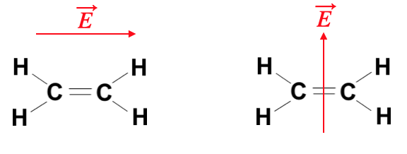
Just consider the above molecule
Consequently also the susceptibility
This coordinate systems is the principle coordinate system of the tensor. The electric displacement field
and in the principle coordinate system of the tensor we obtain
From this it becomes evident, that the displacement field
In anisotropic materials, the direction of energy flow (given by the Poynting vector
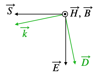
The tensorial nature of the dielectric function has now consequences for the propagation of light. In general different symmetries are considered. If we have for example two of the diagonal elements be equal to each other
then we call the material uniaxial. The system has one optical axis. In case
we call the material biaxial and the material has two optical axes. We will have a look at the meaning of an optical axis a bit later.
A tensor as the dielectric tensor (similar to the tensor of inertia) can be geometrically represented by an ellipsoid with three different half axes as depicted below. This can be done for the refractive index or the dielectric tensor. When doing so with the refractive index, we obtain an index ellipsoid, where the half-axes correspond to the three refractive indices
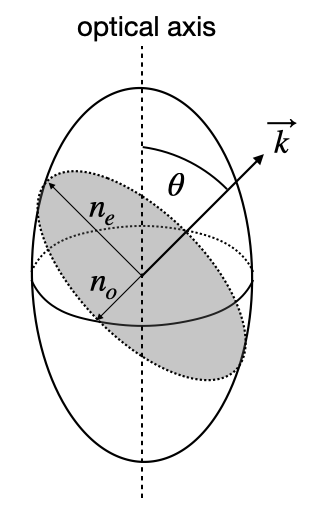
To find out the relevant refractive indices for a certain propagation direction on now undertakes the following steps:
- chose a direction of light propagation with the direction of the wavevector
- construct a plane perpendicular to the wavevector
- take the intersection of this plane with the ellisoid, which is in general an ellipse
- the ellipse has a long and a short axis, which correspond to the direction of the so-called normal modes
- a
Normal modes are specific directions of the displacement field
An optical axis is now a propagation direction, for which the refractive index does not depend on the direction of the electric field. For a biaxial material, there are two distinct directions for a propagation, while there is only one for uniaxial.
Considering now in more detail the propagation of light as a function of the direction of light propagation one obtains a dispersion relation (how the wavenumber depends on teh direction for a given frequency of light). This surface is the so-called k-surface, which in general consists of 2 sheets. This k-surface is obtained from Maxwells equations
which leads to
This equation leads to a system of equations for the components of the wavevector (
The k-surface represents all possible wavevectors at a given frequency in the material. For a uniaxial crystal, this surface consists of two sheets: a sphere representing the ordinary waves and an ellipsoid representing the extraordinary waves. Where these surfaces intersect defines the optical axis, along which the ordinary and extraordinary waves travel with the same phase velocity. This geometric representation helps visualize how light propagates in different directions through the crystal.
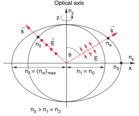
If we select now a specific direction of propagation for the light with the direction of
The ordinary ray corresponds to light where the electric field is perpendicular to the plane containing the optical axis and the direction of propagation, while the extraordinary ray corresponds to light where the electric field has a component parallel to this plane. The association with s- or p-polarization depends on the orientation of the crystal’s optical axis relative to the plane of incidence.
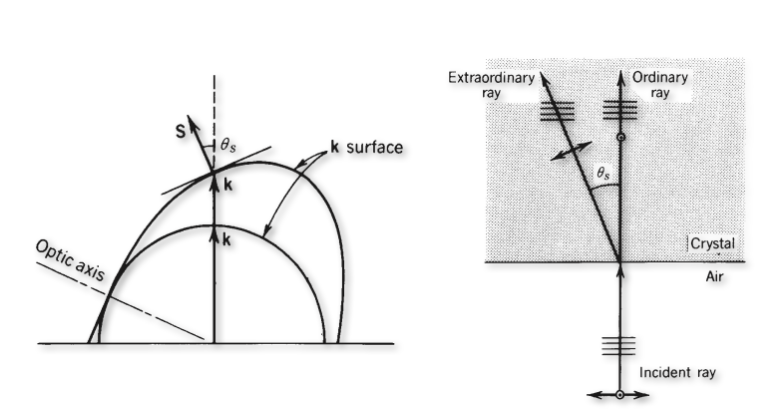
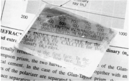
Let’s discuss the sketches above, which show the general case of birefringence. The image on the left side shows an interface between air on the bottom and the anisotropic material on the top. The wavevector is incident from below and is normal zo the surface. Its direction will intersect both k-surfaces and thereby select the ordinary refractive index and the extra-ordinary refractive index for the two different polarization directions. Both waves propgate in the same direction, so their wavefronts are perpendicular to the k-vectors as shown in the middle sketch. Yet, the Poynting vectors go in different direction. The Poynting vector, which points in the direction of energy propagation, is always perpendicular to the k-surface, since the k-surface is an isoenergy surface (think about that for a moment). This means that the beam is split into two beams with parallel wavefronts as indicated. This phenomenon is called birefringence and separates two orthogonal polarizations into two beams as indicated.
This effect is probably best visible, when you put a birefringent material like the common calcit crystal on a newpaper or book. You will immediately see the birefringence in the double images as in the figure above to the right.
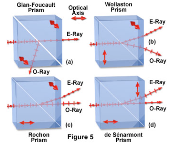
The different refractive index for both polarizations make those materials very suitable for the creating polarizing optical elements like beam splitters. A selection of different polarizing beam splitters is shown in the image below.
Birefringence is often observed in mechanically stressed materials like quickly cooled glasses or stretched polymer foils. The latter is demonstrated in the images below, where we used


Wave retarders
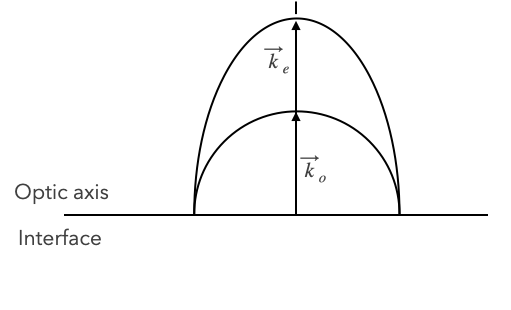
Wave retarders are essential optical components that manipulate the polarization state of light by exploiting the different phase velocities of ordinary and extraordinary waves in anisotropic materials. These components are fundamental in many optical systems, from liquid crystal displays to laser systems and optical communications. Anisotropic materials can now but cut in specific way, for example such that the optical axis is parallel to the interface as in the picture below. Under these circumstances at normal incidence both wavevectors and both Poynting vectors of the polarizations propagate along the same direction. Yet, the p-polarization has a lower phase velocity (long k-vector) than the s-polarization. If now the incident light has now elecric field components parallel and perpedicular to the optical axis which are of same amplitude, then one component of the incident polarization is delayed in its phase with respect to the other comonent.
Let
be the incident electric field of the plane wave travelling along the z-direction with
After a material of thickness
Quarter Wave Plate
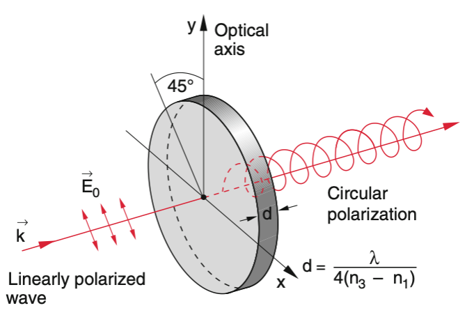
If we design now a material of a certain thickness such that the phase shift is
The crystal thickness is, however, not restricted to this minimal thickness, but to any thickness which creates a phase difference of
If the two elecric field components are not of equal amplitude, then a quarter wave plate will generate elliptically polarized light. Note that if you send circular polarization to a QWP, linearly polarized light will be created.
Half Wave Plate
A half wave plate creates a phase difference of
When linearly polarized light is incident at an angle
The minimum thickness of a half wave plate is given by:
Similar to the quarter wave plate, any thickness which creates a phase difference of
